
CNC maintenance technology (computer numerical control) is not only the premise to ensure normal operation, but also plays a huge role in promoting the development and improvement of CNC technology, so it has become a specialized subject at present.
Any CNC machines are process control equipment, which requires it to work accurately at every moment of real-time control. Failure and failure of any part will cause the machine to stop, resulting in a production stoppage and machine breakdown.
Therefore, it is very necessary to do the device preventive maintenance with complex principles and precise structures such as the numerical control system. Especially for imported CNC machine tools, most of which cost hundreds of thousands to tens of millions of dollars. In many industries, this equipment is in key jobs.

The following tasks have to be done every day, assuming regular usage hours:
1. Inspect the pressure and level of lubricant. Top up if required. Guaranteed machine lubrication.
2. Check the coolant level; If it is not enough, please add coolant in time. Use a coolant refractometer to ensure the coolant and oil ratio is maintained.
3. Clean out the coolant disposal tray. Check the oil level of the pneumatic triple piece, which is about 2/3 of the height of the entire oil pipe. The water vapor in the pneumatic triple oil filter tank is discharged from the drain switch every day.
4. Check for moisture in pneumatic air. Drain moisture if it is detected.
5. Check the pressure of pneumatic air with the pneumatic pressure gauge. Check the air pressure, loosen the adjustment knob, and adjust the pressure according to the principle of right-handed pressure increase and left-handed decompression, generally set to 5~7KG/CM2. The pressure switch is usually set to 5KG/CM2. When the pressure is lower than 5KG/CM2, the alarm will appear, and the system will display a 'LOW AIR PRESSURE' alarm. After the pressure rises, the alarm message will disappear.
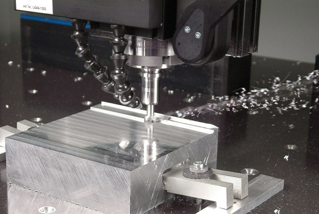
6. Wipe the complete machine with a clean rag. Remove the cutting and oil stains on the worktable, inside the machine tool, and on the three-axis telescopic shield.
7. Check the output of the voltage stabilizer. Ensure it adheres to the required specifications.
8. Check panel cooler temperature.
9. Observe noises, bangs, or any other anomalies in machine operation.
10. Watch out for any overheating signs during machine operation.
11. Check whether the air blowing in the inner taper hole of the spindle is normal, wipe the inner taper hole of the spindle with a clean cotton cloth, and spray light oil.
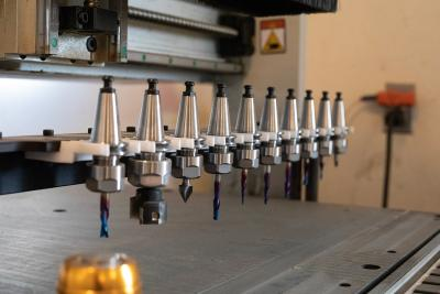
12. Clean the tool magazine tool arms and tools, especially the tool claws.
13. Clean exposed limit switches and bump blocks.
14. Check whether all signal lights and abnormal warning lights are normal.
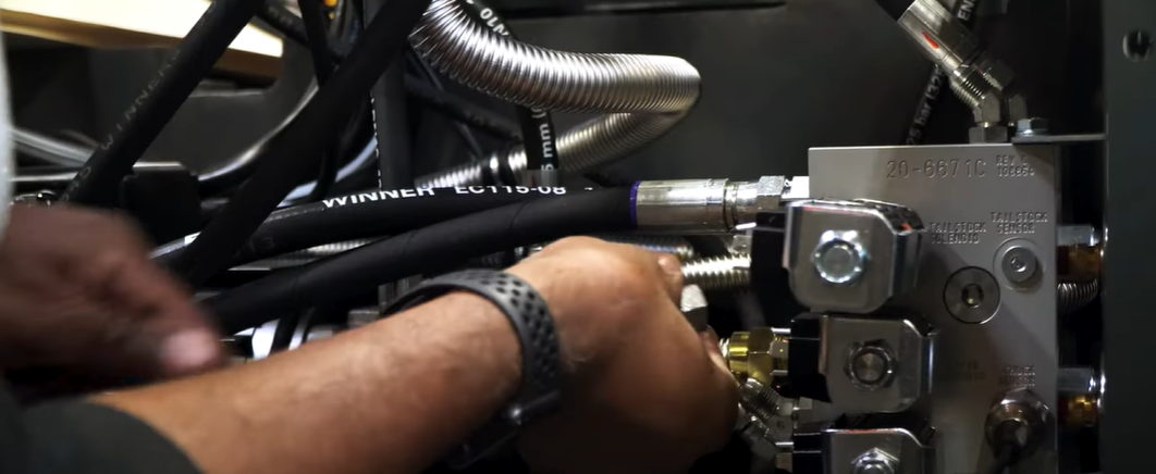
15. Check whether there is leakage in the oil pressure unit pipe.
16. The machine tool should be cleaned after the daily work is completed.
17. Keep the environment around the machine clean and tidy.

The following maintenance tasks have to be done on a weekly basis:
1. Clean the complete machine shop, especially the area surrounding the machine.
2. Check for any evidence of lubricant, oil, or coolant leakage.
3. Check and ensure all cooling fans are working properly. These include spindle motor fans, cooling system fans, hydraulic motor fans, and hydraulic pressure. Clean the air filter screen of the heat exchanger, the filter screen of the cooling unit, and the lubricating oil pump.
4. Perform a visual inspection of machine components. Apply grease or appropriate lubricant to parts that seem dry.
5. Check whether tool heads are held securely in the tool changer and clean or not.
6. Lubricate the v-groove, plungers, slider cap, extractor forks, keys, and springs of the tool changer.
7. Check if all electrical components such as switches and lights are working properly.
8. Check whether the three-axis mechanical origin is offset.
9. Check whether the tool changer arm of the tool magazine or the tool magazine rotates smoothly.
10. If there is an oil cooler, check the oil cooler oil. If it is lower than the scale line, please add oil cooler oil in time.
11. Check the set temperature of the oil cooler, it is recommended to set it between 26-28 degrees.
Maintenance checks that should be done every month include the following:
1. Clean out the chip collector close to the coolant tank.
2. Inspect, remove, and adjust jaws, chucks, and fixtures.
3. Clean or replace air filters as required.
4. Check the condition of tool heads and change them if necessary.
5. Inspect, lubricate, tighten, and adjust chains and conveyors in the machine.
6. Clean various fans of the machine to prevent dust accumulations.
7. Inspect the logs of oil, lubricant, and coolant. Check for any anomalous consumption.
8. Clean radiator grills of dust and debris.
9. Check the lubrication of the X, Y, and Z three-axis track, and the track surface must be well-lubricated.
10. Check and clean limit switches and bumps.
11. Check whether the oil in the oil cup of the knife cylinder is sufficient. If it is insufficient, please add it in time.
12. Check that the signs and warning nameplates on the machine are legible.
CNC machine maintenance checks that need to be done semi-annually:
1. Disassemble the triaxial anti-chip guard, clean the triaxial oil pipe joint, ball lead screw, and triaxial limit switch, and check whether it is normal. Check whether the effect of the hard rail wiper blades of each axis is good.
2. Check whether the servo motor and head of each axis are running normally and whether there is any abnormal sound.
3. Replace the oil of the hydraulic tank and the oil of the deceleration mechanism of the tool magazine.
4. Test the clearance of each axis, and adjust the compensation amount if necessary.
5. Clean the dust in the electric box (make sure the machine tool is turned off).
6. Comprehensively check whether all contacts, connectors, sockets, and switches are normal.
7. Check and adjust the mechanical level.
CNC machine maintenance checks that need to be done annually:
1. Check whether all keys are sensitive and normal.
2. Clean the cutting water tank and replace the cutting fluid.
3. Check the vertical accuracy of each axis and decide whether it needs to be adjusted.
4. Remove the coolant cylinder tank for inspection.
5. Clean out the coolant cylinder for debris, inspect for bacteria or fungal growth, and clean the tank.
6. Drain the used lubricant, clean the lubricant housing, and refill it.
7. Inspect for the presence of contaminants in pneumatic oil. Change it if required.
8. Replace all oil filters.
9. Run software simulations to check the alignment and indentation of tools.
10. Use software to quickly reverse the axis of the tool head to check for backlash. If the tool head experiences a backlash effect, further maintenance is required.

1. After starting the machine, it must be preheated for about 10 minutes before processing. Machines that will not be used for a long time should extend the warm-up time.
2. Check whether the oil circuit is smooth
3. Place the table and saddle in the center of the machine before shutting down the machine (move the three-axis travel to the middle of the travel of each axis).
4. Keep the machine tool dry and clean.
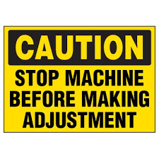
Note: The maintenance and repair of the equipment should be carried out by professional engineers.
1. The grounding protection system should have good continuity to ensure personal safety.
2. Regularly check the essential components such as circuit breakers, contactors, and single-phase or three-phase arc extinguishers. If the wiring is loose or the noise is too loud, find out the reasons and eliminate hidden dangers.
3. Make sure that the cooling fan in the electric cabinet operates normally, otherwise, it may cause damage to the vital components.
4. The fuse is blown and the air switch is frequently tripped. The cause should be found and eliminated in time.
5. Servo drive battery replacement
The absolute control system data is maintained by the servo drive battery. When the battery voltage is too low (warning 9F), the drive battery must be replaced. Please order the same type of battery unit as soon as possible, and keep the drive power on. Please turn on the power of the drive unit 30 minutes before replacing the battery, and complete the battery replacement within 1 hour.
1. Confirm that the input power supply has been cut off and that the power supply of the replaced drive unit has been turned off.
2. Pull out the battery plug connected to the battery socket of the drive unit.
3. Press the side of the battery with your fingertips, push the battery horizontally, and then take it out.
4. Connect the plug of the new battery to the battery socket of the drive unit.
5. Install the battery on the drive unit.

On-site maintenance is to diagnose the failure of the CNC machine tool (mainly the CNC part), find the fault location, and replace it with the corresponding normal spare parts, so that the machine tool can resume regular operation.
The key to this process is the diagnosis, that is, to detect the system or peripheral circuits, determine whether there is a fault, and point out the exact location of the fault for fault location. From the positioning of the whole machine to the patch panel, in some cases, even to the components. This is the main part of the whole maintenance work.
Usually, when the data is relatively complete, the fault can be judged through data analysis, or the interface signal method can be used to judge the parts that may fail according to the fault phenomenon, and then check the parts one by one according to the specific characteristics of the fault and this part, and make a preliminary judgment.
In practical applications, it may be possible to use one method to find and eliminate faults, and sometimes multiple methods are required. The degree of mastery of various methods of judging fault points mainly depends on the depth of mastery of the principles and structures of faulty equipment.
When the numerical control system fails, the fault signal and corresponding information are generally given on the display screen or operation panel. Usually, the operation manual or adjustment manual of the system has a detailed alarm number, alarm content, and processing method.
Because the alarm settings of the system are single, complete, strict, and clear, maintenance personnel can handle them by themselves according to the information and processing methods given after each alarm.
According to the electrical characteristics of the machine tool, the machine tool manufacturer applies PLC programs to display some faults or operation information that can reflect the electrical control of the machine tool interface with specific signs, and give them through the display, and can see more detailed alarm descriptions through specific keys. This type of alarm can be handled according to the troubleshooting manual provided by the machine tool factory, or the operation panel or programmer can be used to find out the corresponding signal state according to the circuit diagram and PLC program, and find the fault point for processing according to the logical relationship.
Troubleshooting with no alarm or no alarm When the PLC of the system cannot be run, the system has stopped or the system does not alarm but works abnormally, it is necessary to analyze and make a decision based on the system status information before and after the failure and using the theoretical basis that has been mastered. correct judgment. This fault diagnosis and troubleshooting method are described below.
1. Visual inspection
Visually inspect the faulty board, carefully check whether there is a blown fuse, charred components, smoking, or cracking and whether there is a foreign body open circuit. In this way, it can be judged whether there are overcurrent, overvoltage, short circuits, and other problems in the board.
2. Touch
Touch and shake the components with your hands, especially the resistance, and capacitance, whether the semiconductor device has a loose feeling, so as to detect some problems of soldering.
3. Power-ups
First, use a multimeter to check whether there is an open circuit between various power supplies.
If there is no, you can connect to the corresponding power supply. Visually check whether there is smoke, ignition, etc., and touch the components for abnormal heat.
Failure, and narrow the scope of maintenance.
For example: when troubleshooting a factory in Harbin, the CNC system and PLC of the machine tool are running normally, but the hydraulic system of the machine tool cannot be started. Use the programmer to check that the PLC program is running normally and that the required signal states meet the startup conditions.
During further inspection, it was found that the PLC signal status was inconsistent with the markings on the drawings and equipment. The machine stopped and pulled out the circuit board for inspection. It was found that the address of the two output boards of the PLC was wrong, and the positions of the other two were wrong. After the exchange, the machine tool ran normally.
For the SIMATIC S5 programmable controller used by the machine tool with this failure, as long as the address is correct, no matter how the position of the circuit board is arranged, the system can run normally. Still, the corresponding executive components and signal sources must be correctly corresponding.
Corresponding errors will cause malfunctions and even destroy the machine tool. In addition, according to the failure phenomenon provided by the user, combined with their own on-site observation, and using the working principle of the system, a correct judgment can be made quickly.
4. System parameter check method
Nowadays, the self-diagnosis function of the operating system of CNC machine tools is getting stronger and stronger, and most of the faults of CNC machine tools can be diagnosed. When the CNC machine tool fails, sometimes the alarm information is displayed on the display, and sometimes there are alarm devices on the CNC device, the PLC device, and the drive device, such as the alarm light will flash, buzzer, and so on.
At this time, first, check the maintenance manual and check the corresponding parameter settings. The loss and incorrect setting of system parameters will cause the change or failure of the machine tool performance.
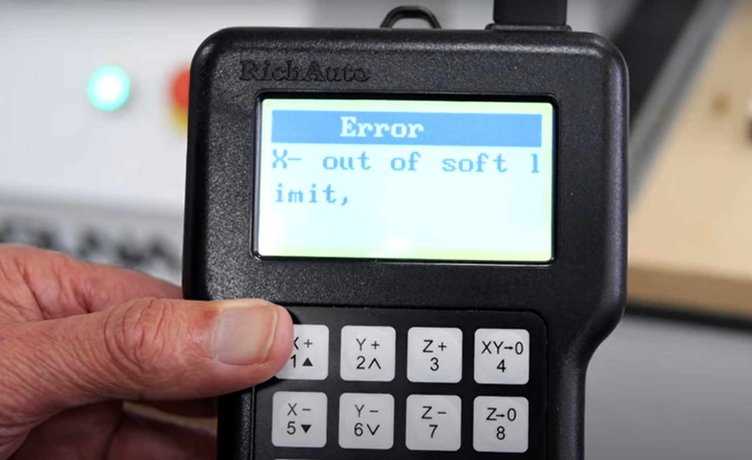
For example, in the automatic machining of the FANUC system, the machine tool rest stops moving and the screen displays 500 and 501 alarms. Check the parameter manually to find out that the corresponding parameters are stored stroke limit positive and negative limits. At this time, the machine tool can be changed to manual shaking. When the tool holder reaches the correct stroke range and corrects the parameters, the alarm can be removed.
5. Reset machine method
In the process of processing, due to the system alarm caused by the instantaneous fault, the fault can be cleared by hardware reset or turning on and off the system power in turn. The system must be initialized and cleared. Before clearing, you should pay attention to copying and recording important data. If the fault cannot be eliminated after initialization, perform hardware diagnosis.
6. Measurement diagnosis method
Measurement is the basic method for diagnosing equipment failures. We can use instruments such as multimeters, oscilloscopes, and logic testers to measure electronic circuits.
For example, when determining the phase sequence of the three-phase power supply of the numerical control system, the phase sequence table can be used for measurement, that is, the three-phase power line is connected to the phase sequence table. When the phase sequence is correct, the phase sequence table rotates clockwise, and vice versa. It can also be measured with a two-channel oscilloscope. If the phase sequence is correct, the waveforms of each two phase are 120° out of phase.
According to the system circuit diagram and machine tool circuit diagram, the voltage, power supply, pulse signal, etc. of the faulty part are measured to determine the fault. For example, the input voltage of the power supply exceeds the limit, causing the power supply monitoring to use a voltmeter to measure the network voltage or to use a voltage tester to monitor in real-time to eliminate other reasons.
If the position control loop fails, the oscilloscope can be used to check the signal state of the measurement loop, or the oscilloscope can be used to observe whether the signal output is phase-missing and whether there is interference.
For example, when a factory in Shanghai is troubleshooting, the system alarms, and the hardware of the position loop is faulty.
The oscilloscope is used to check and find that there is an interference signal. We use the method of connecting capacitors in the circuit to filter them out to make the system work normally.