Efficiently running CNC Planer Machine parts and functions is a must clearly. This blog is based on practical strategies. We will address calibration, lubrication and software upgrades.
Precision is paramount. Techniques will be presented in-depth. Update your CNC planer for best results. All right, let's delve into the details!
The bottom of the CNC planer machine is where servomotors and other vital parts are positioned for a stable foundation. It is composed of precision-made steel plates that enhance the strength and integrity of the construction.
By means of vibration dampeners, intelligently placed, the operating noise is minimized. The base can have the coolant reservoirs for the temperature control.
Frame of the machine is strengthened and guide rails and worktable are then mounted. Integrated sensors are checking positional accuracy.
The base of the device features hydraulic systems allowing for smooth motion. The design is composed of chip disposal systems for tidiness. Power supply units embedded in the base ensure a regular charging.
The table in the CNC planer machine runs on the guide rails, driven by the stepper motors. It contains T-slots for fastening of workpieces. Smoothness of the table motion is made possible because of precision bearings. Embedded encoders track positioning with high accuracy.
It has a surface that has been hardened for longevity. Limits of movement can be defined by an adjustable stop. The clamping mechanisms are also integrated. An integrated lubrication channel reduces friction. It is resistant to the heavy load without any deformation.
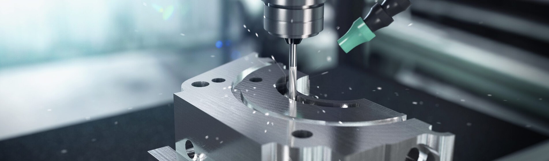
The cutting head of a CNC planer is designed to hold multiple cutting tools. In operation, it rotates with a high speed, driven by the main spindle motor. Tool holders that are on the cutter head will always secure proper tool positioning.
This rapid tool-changing feature enables you to easily switch between different tools. High quality bearings facilitate a seamless rotation. Composite heating ducts avoid overheating. The cutter head design improves the accuracy through vibration decrease.
The sensors notice the rotational speed and tool wear. Its small size is designed to likewise perform the best. The cutter head makes for precise and thorough material removal.
The motor of a CNC planer machine powers the rotary spindle and feed mechanisms. It comes with a variable frequency drive (VFD) for speed regulation. High-torque output provides power for heavy-duty cutting tasks. The motor’s structure includes thermal protection systems.
As it connects with the control unit, it enables very fine-tuned speed variations. The cooling fans eliminate the overheating issue arising during operation. Vibration isolators lessen the audible noise of the machinery. Integrators using encoders provide real-time feedback.

Lead screws of the CNC planer machine provide the accurate linear motion. Known as hardened steel, they don’t wear out that easy. The movement along the rails is guaranteed by linear bearings. Integrated lubrication systems decrease friction among connected components.
Position sensors can precisely follow movement. The rails are arranged with laser alignment precision. They are designed to bear the load on the table as well as the cutting part. Vibration dampeners reduce vibration mitigation.
CNC planer machine parts require regular lubrication in order to operate. Apply oil to linear bearings, guide rails and lead screws. Install an automatic lubrication system with proper metering. Carry out scheduled inspections of oil levels in reservoirs to ensure uninterrupted supply.
Check and clean lubrication channels to ensure that they are not blocked. Use only the best lubricants to facilitate a hustle-free operation. Lubricate spindles and ball screws to mitigate friction.
Make sure that it is applied to every moving element. Strive for the best viscosity for proper functioning. The living time of components is increased by proper lubrication.
When CNC planer machine components are aligned it enhances the precision. Use a dial indicator to check the table parallelism. Adjust guide rails using laser alignment tools. Calibrate the spindle axis alignment with precision levels. Inspect and if necessary, adjust misalignment in cutter heads.
Use feeler gauges for specific measurements. Align motor shaft with a straightedge check. Frequently make sure the tracks keep in alignment to avoid excess wear.
Maintain strict tolerances for each part. Right alignment leads to a rise in the precision and productivity within the field of machining.
Repeated cleaning of CNC planer machine parts helps avoid clogging. Install compressed air along the guide rails to blow away the debris. Use industrial wipes to clean table surfaces. Unload the chips from the cutter head housings. Set up a vacuum unit to clear the base and motor.
Wipe down control panels and screens frequently. Check and clean coolant reservoirs and passages. Employ mild cleaners, which won’t cause harm. Keep clean to allow performance at its peak. Regular cleaning prevents malfunctions from happening and increases durability.
Carry out comprehensive inspection of CNC planer machine elements. Use the borescope to carry out the inspection of internal parts. Check the guide rails and bearings for signs of wear and tear. Check the sharpness of the cutter heads and look for any damages.
Check motor performance with a range of diagnostic tools. Check lubrication systems to ensure that they are operating properly. Check electrical connections for the signs of wear. Use thermal imaging to locate the hot components to avoid their failure. Write down the results and plan the work required.
Regular inspections make it possible to identify problems at the earliest stage. Keep a journal that can serve as a reference in future.

Advancing feed speeds of CNC planer machines improves the operation in terms of efficiency. Adjust the feed rate to fit the speed of the spindle. Utilize G code commands to adjust the feed rate. On the control panel there are displays that indicate the feed rate.
Provide for an equal chip load throughout the process. Switch feed rates with cutting tool material. Stepper motors should be used for better control. The feedback system can be installed to make the adjustments in real time. Use diagnostic software to interpret the collected data for the feed rate. At optimal speed, feed ensures keeping tools sharp.
Selecting accurate cutting tools raise CNC's efficiency. If you have to work with harder materials, go for carbide-tipped tools. Adjust suitable HSS tools for softer metals. Use the automated sharpeners to have the right sharpness of these tools. Make sure to use indexable inserts to decrease downtime.
The application of multi-tooth cutters can bring about faster material removal. Watch over tool wears with integrated sensors. Modify the tool angles for different cutting operations.
According to the CNC planer machine process, the software regulates the effectiveness of the machine. Use CAD/CAM software for compact design integration. Adapt control policy for real-time decision making. Supervise HMI displays to monitor machine status.
Use G-code to ease the process of generating precise machining instructions. Utilize software-based algorithms for toolpath optimization. Integrate ERP systems with workflow management tasks. Employ DNC system for smooth transitions of the program.
Measure the production metrics with data from SCADA systems. Frequent software updates will be better for the future of the system.
The cooling systems must be more efficient to ensure proper function of CNC planer. Apply flood coolant in high-speed work procedures. Consider mist coolant use in lower-level applications. Check out coolant flow rates by measuring them with digital gauges.
Integration of chip conveyors makes debris removal easily and effectively. Machining deep holes can be facilitated with through-spindle coolant. Ensure to clean coolant filtration systems on a regular basis to avoid potential issues. Check temperature using infrared sensors. Adjust coolant nozzles to ensure its uniform distribution.
Optimization toolpath will increase the planer's CNC efficiency. Apply CAM to get the best toolpaths. Use helical interpolation to achieve more accurate cuts with fewer anomalies.
See to it that trochoidal milling is carried out in order to decrease tool stress. Adjust the feed rate within the toolpath for equilibrium. Apply the ramping technique for tool entry to provide a gradual startup. Check toolpath simulation for possible errors. Incorporate a retraction move to reduce air-cutting.
Make use of multi-axis toolpaths for consolidation of complex geometries. Gradually upgrade toolpath algorithms for facilitated production.
|
Technique |
Key Components |
Advantages |
Examples/Brands |
Efficiency Impact |
|
Feed Rates |
High-speed spindles |
Faster production |
Haas, Mazak |
High |
|
Cutting Tools |
Carbide, Diamond |
Improved durability |
Kennametal, Sandvik |
High |
|
Software Controls |
CAM Software |
Precision, automation |
Mastercam, SolidCAM |
High |
|
Cooling Systems |
Flood, Mist, Air Blast |
Prolongs tool life |
Kool Mist, FogBuster |
Medium-High |
|
Toolpath Optimization |
CAD/CAM Integration |
Reduced cycle time |
Autodesk, Fusion 360 |
High |
Table on Techniques to Improve Efficiency of CNC Planer Machines!
Get an accurate 15000 RPM cut speed by calibrating the spindle speed. Employ the use of carbide inserts with 45-degree rake angle. Include commands for G-code for the incremental adjustments. Keep feed rate equal to 0.02 mm per tooth. Let the tool holder's maximum runout be 0. 003 mm.
Measure the part using dial indicators and ensure accuracy. Align cutting paths using laser alignment instruments. Please go to the machine control panel to double-check the tool offset. Accurate measurements reduce the amount of material wasted.
Minimize waste setting the cut depth to 3mm to cut the product precisely. Apply CNC programming to optimize toolpaths. Apply nested cutting methods to get the most from the least material amount. Adjust spindle speed relative to the material hardness.
Install chip loading monitoring systems in real time for feedback. Implement a vacuum system for efficient debris elimination. Apply multi-axis moves to decrease the amount of extra material waste.
Use optical inspection systems to find the level of cut quality. Optimize cutting parameters to attain higher efficiency.
Speed it up by adjusting spindle RPM to match the material properties. Apply VFDs in the speed control. Track the speed of cutting with the help of tachometers. Set up the feed rate with the use of CNC software parameters. Balance the cutting force by modulating the spindle torque. Incorporate advanced high-speed machining of complex components.
Keep checking from time to time in the control interface to see what the speed settings are. Use adaptive control mechanisms for real-time adjustments. Proper speed regulation eliminates tool wear.
Keep tools sharp by using automatic tool sharpeners. Using magnifying tools, check cutting edges on parts with wear. Change static pads when they are worn by 20%. Coat carbide tools for longer duration. Control tool condition by in-process sensors.
Tool pre-setters should be used tooling for precise length measurements. Establish a tool management system for efficient inventory control. Modify the cutting parameters to fit to the tool sharpness. Tool maintenance every time guarantees proper cutting.
With the use of a digital micrometer, you can measure the spindle runout. Put to use the granite surface plate for checking flatness. Take advantage of a dial indicator to check the alignment of the linear guides. Use a laser interferometer as a distance measuring tool together with high precision.
Use a torque wrench for even fasteners tightening. Visually check tool holders with a precision arbor. Apply calibration tools frequently to ensure accuracy. Calibration tools maintain operation accuracy among all machined parts.
Use a Renishaw probe as a positioning tool for workpiece. Set a height gage for Z-axis calibration. Apply a CMM (coordinate measuring machine) for 3D accuracy checks.
Put a digital caliper that can measure for external and internal dimensions. Use an optical comparator in edged alignment. Strain gauges will be used to determine machine deflection.
Include a bore gauge with the capability of internal diameter checks. Ensure the accuracy of the measurement devices by calibrating them from time to time. The measurement devices are essential to get the necessary information for modifications.
Manipulate the parameters of the machine through using CNC control software. Calibration by using G-code commands for accuracy. Set the backlash compensation parameters in the software. Make use of CNC software to hone feed rate as well as spindle speed.
Integrate software-based thermal compensation. Integrate adaptive control for real-time performance optimization. Run the diagnostic software for error detection. Adjust servo motor settings in software. Software updates guarantee foolproof management of all the machine’s operations.
Conduct test cuts on a standardized piece of the material block. Using micrometer, measure cut details. Surface finish must be checked by a profilometer. Test out cut data for the deviations. Set tool offset based on test cut results. Measure spindle load during test cuts.
Compare the actual dimensions with CAD requirements. Check the edge under the toolmaker's microscope. Data cuts help to verify calibration and fix any discrepancies.
Adjust spindle speed to within 20 rpm of target. Reduce feed rate at 0.01 mm increments. Adjustments with a dial indicator will improve table alignment precision.
Calculate the cutting tool angles to the nearest degree with the aid of a protractor. Adjusting the machine leveling feet allows for stable operation. Monitor electrical signals using an oscilloscope.
Optimize the coolant flow rate for the best temperature regulation. Regularly check and appropriate linear encoders. Adjustment guarantees top as well as accurate performance.
|
Calibration Method |
Tools Required |
Precision Level |
Time Required |
Common Brands |
Frequency Needed |
|
Calibration Tools |
Dial Indicators, Probes |
High |
Moderate |
Mitutoyo, Renishaw |
Regularly |
|
Measurement Devices |
Micrometers, Calipers |
Very High |
Moderate |
Starrett, Fowler |
Regularly |
|
Software Adjustments |
CNC Software |
Very High |
Low |
Siemens, Fanuc |
Occasionally |
|
Test Cuts |
Sample Workpieces |
High |
Moderate |
Any material |
Regularly |
|
Fine Tuning |
Manual Adjustments |
Very High |
High |
Hand tools |
As needed |
Table on How to Calibrate CNC Planer Machine Parts for Maximum Precision!
Continuously modify CNC planer software to version 10.2.5. Get the updates from the manufacturer’s site. Use a USB 3. 0 drive for instant shuttling. Backup existing settings before installing. Make sure that it is compatible with the model of control unit. Track performance via HMI display.
Updating the firmware on each connected device is a must. Confirm the updated through the system diagnostics. Do a restart to make the changes effective.
Develop complex features such as the real time adaptive control. Consider AI algorithms for predictive maintenance. Integrate CAD/CAM software for one-touch transfer of designs.
Take advantage of IoT for remote monitoring. Implement superior toolpath generation for complex contours. Provide the operators with AR tools to utilize. Changing parameters using a touch-screen interface. Integrate data analytics of real time for performance improvement.
New software must be compatible with the Siemens SINUMERIK 840D control unit. Check driver support for a linear encoders and servo motors. Confirm the compatibility of our software with CAD/CAM systems. Provide support to the Ethernet and RS-232 communication protocols.
Include PLC systems test integration. Make sure the software is compatible with the CNC pre-setters. Check hardware compatibility for remote access. Compatibility secures well-run software.
First, download the installation package on the PC. Connect the CNC machine with Ethernet cable. Use the utility software provided by the manufacturer. On-screen instructions will take you through the installation process. Enter machine specific parameters during installation process.
Monitor installation by way of diagnostic LEDs. Show installation efficiency success through test cuts. Update the machine firmware if necessary. Keep a record of the changes for further reference. Ensure data security during this process.
Finally, optimizing CNC Planer Machine Parts and Functions improves the efficiency. Detailed calibration and constant lubrication are crucial. Software updates are way of getting new features. The accuracy of the cutoff and waste disposal are what matters.
Make sure you stay up to date with the current practices. They prolong the machine life. Visit CNCYANGSEN for more tips. Use these methods to get the best out of them. It’s time to bring out the performance of your CNC planer.

Tel : +86-592-6682467
WhatsApp : +86-18359729483
Email : info@cncyangsen.com
Address : No. 586-590 Shanbian Rd. Dongfu Industrial Zone Haicang Dist, Xiamen, Fujian Province, China 361027