In the world of precision engineering, where a hair's breadth can make the difference between success and failure, the role of CNC measuring tools is nothing short of critical. These tools serve as the silent sentinels, ensuring that every intricate detail of a design is translated flawlessly into reality. So, let's dive into the fascinating realm of CNC measuring tools and explore the marvels they bring to the manufacturing table.

Picture this: a machine that combines the precision of a skilled craftsman with the efficiency of a supercomputer. That's the essence of a Coordinate Measuring Machine or CMM. It's like the Sherlock Holmes of the manufacturing world, solving dimensional mysteries with uncanny accuracy.
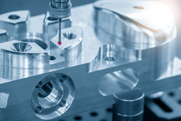
The CMM stands tall as the cornerstone of CNC measuring tools. Its mission? To measure objects with astounding precision, enabling manufacturers to ensure that their creations align flawlessly with the intended specifications.
Imagine you've just designed a complex component for a spacecraft. Every curve, angle, and indentation matters. The CMM comes into play by probing the object's surface with pinpoint accuracy. Using a probe head, it maps the coordinates of various points on the object, constructing a 3D model in the process. This model is then compared to the design blueprint, revealing any deviations that might have occurred during manufacturing.
But here's the magic: it's not just about pinpointing deviations. The CMM also helps engineers analyze the overall quality of their manufacturing processes. It's like a doctor giving your production line a check-up, identifying areas for improvement and ensuring that every piece meets the gold standard.

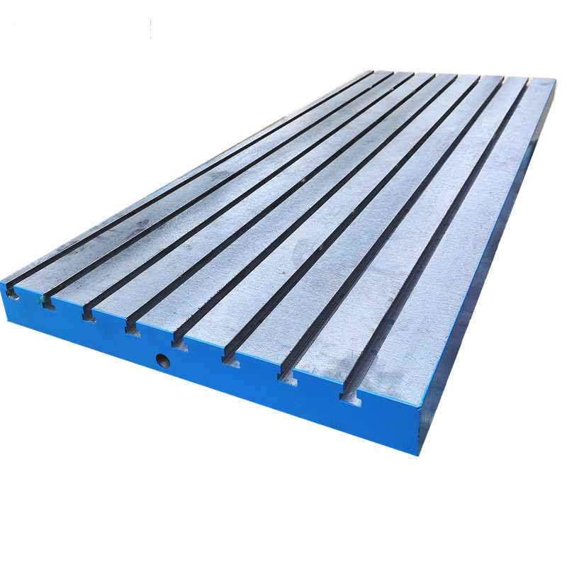
Think of a Surface Plate as the canvas upon which precision artistry takes place. It's not merely a flat surface; it's a foundation of accuracy that sets the stage for perfection. This unassuming piece of equipment holds the key to ensuring that measurements are accurate to the finest detail.
In the grand symphony of manufacturing, the Surface Plate plays the role of the conductor's podium. It provides a stable and precisely leveled platform for measuring instruments, allowing engineers to take measurements without the interference of uneven surfaces.
Imagine you're crafting a mechanical masterpiece using a CNC milling machine, a gearbox that needs gears meshing seamlessly to avoid future mishaps. The Surface Plate steps in by offering a perfectly flat and level stage for your measurements. It's a backstage pass to precision.
Engineers place the component on the Surface Plate and employ various CNC measuring tools like micrometers and height gauges to take measurements. The flatness and levelness of the plate ensure that measurements are consistent, free from the distortions that might occur on irregular surfaces. In essence, the Surface Plate creates a controlled environment, turning the art of measurement into an exact science.

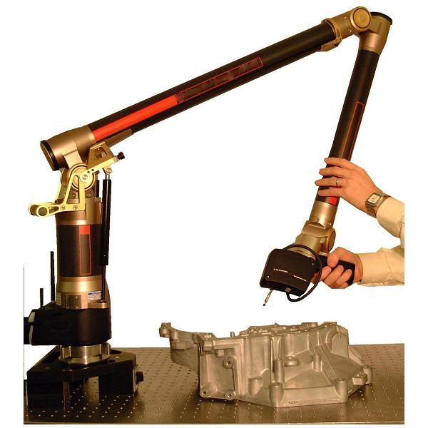
Enter the realm of the future: the Laser Scanning Arms. These high-tech contraptions bring the power of lasers to the world of measurement, revolutionizing how we capture data and ensuring that even the most intricate designs are replicated with utmost fidelity.
If the CMM is Sherlock Holmes, then the Laser Scanning Arm is the technological Watson. Armed with lasers and sensors, it captures intricate details in a way that even the keenest human eye might miss.
Consider a scenario where you're tasked with recreating a sculptor's masterpiece, a statue that's a work of art and engineering. Traditional methods might struggle to capture every curve and contour, but not the Laser Scanning Arm.
This futuristic tool wields lasers to scan objects, creating a digital representation of the physical world. Every nook, cranny, and intricate detail is captured in a matter of moments. It's like a 3D printer in reverse, turning reality into a digital masterpiece.
But the real charm lies in its versatility. Laser Scanning Arms are not limited to inanimate objects; they can measure complex surfaces, organic forms, and even moving components like CNC Lathe. Whether it's inspecting an aircraft turbine blade or analyzing a customized medical implant, these arms bring a level of precision that's reshaping industries.
Imagine a tool that holds the power to grant or deny passage – that's the Go/No-Go Gauge. It's a gatekeeper of accuracy, ensuring that components meet the exact specifications required for them to function seamlessly together.
The Go/No-Go Gauge embodies a binary verdict. It doesn't fuss with measurements; instead, it answers a fundamental question: does the component fit within the allowable tolerances?
Let's envision a scenario in the automotive realm. Picture a piston that needs to slide smoothly into its cylinder. The Go/No-Go Gauge steps in to decide the piston's fate. If the piston effortlessly slides through the "Go" side but refuses to budge on the "No-Go" side, it's a clear sign of precision.
This tool simplifies the complexity of measurement by eliminating the need for numbers. It's like a traffic light for engineers – green for approval and red for reassessment. In a world where precision is paramount, the Go/No-Go Gauge provides an instant verdict that keeps the production line moving with confidence.

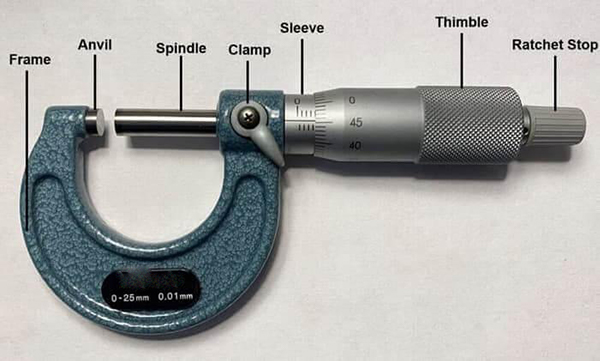
If the Go/No-Go Gauge is the tool of binary decisions, then the Micrometer is the maestro of minutiae. This device dives into the realm of microscopic measurements, revealing the tiniest details that contribute to flawless execution.
The Micrometer is a magician's wand for those who seek to measure the seemingly immeasurable. It unlocks the mysteries that lie within the minute dimensions of a component.
Consider a scenario where aerospace engineers are crafting a turbine blade. The blade's curvature and thickness must adhere to the strictest standards. This is where the Micrometer enters the scene with its slender jaws. It delicately measures dimensions with precision down to micrometers – a fraction of the width of a human hair.
But it's not just about measurements; it's about consistency. A series of measurements can reveal variations that might go unnoticed otherwise. The Micrometer transforms a component from an abstract blueprint into a tangible entity, ensuring that every detail is accounted for.
Meet the multitool of the measuring world – Calipers. Like a Swiss Army knife, Calipers come in various forms, each designed to tackle specific measurement challenges with finesse. It's a versatile companion in the quest for accuracy.
Calipers are the chameleons of measurement. They adapt to different scenarios, providing a flexible yet accurate means of gauging dimensions.
Imagine crafting a medical implant. The Calipers step in to measure the implant's length, width, and even its depth. This versatile tool offers options – vernier, digital, or dial calipers – tailored to the nature of the task.
With Calipers, engineers don't need to rely solely on the precision of a single tool. They can choose the best-suited variation to ensure accuracy. From measuring the diameter of a screw to evaluating the thickness of a sheet of metal, Calipers flex their adaptability muscles, making them a staple in the arsenal of CNC measuring tools.
Venturing into the realm of fluid dynamics, the Air Gage takes center stage. This tool relies on air as its measuring medium, embracing the subtle power of pressure differentials to assess dimensions that might challenge traditional tools.
The Air Gage is like a whisperer or vertical CNC machine to components that require a gentle touch. Its use of air pressure to detect minute variations sets it apart in the world of CNC drilling machines and other measuring tools.
Consider a situation where a medical device needs a precise bore diameter. Traditional tools might struggle, but the Air Gage comes to the rescue. By measuring the pressure difference between the gage and the component, it accurately determines the diameter without causing any damage.
This tool's reliance on air's innate properties showcases the ingenuity of precision engineering. It's a reminder that sometimes, a gentle breath can reveal the most intricate details, and in the world of CNC measurement, accuracy comes in many forms.

In the symphony of precision engineering, the orchestra of CNC measuring tools plays a diverse array of instruments and the types include CNC lathe, vertical CNC machine, and CNC drilling machine. Let's continue our exploration by delving into the unique capabilities of more essential tools that grace this remarkable ensemble.
Imagine a tool that can magnify, measure, and compare components all in one glance – that's the Optical Comparator. It's like a magnifying glass with a PhD in precision, revealing deviations that might escape the naked eye.
The Optical Comparator is the detective of the measuring world, unraveling the mysteries hidden within the tiniest of details. Its ability to create enlarged images of components allows engineers to spot even the slightest imperfections.
Picture a scenario where intricate gears need their teeth examined for flawless meshing. The Optical Comparator enters the scene by projecting an enlarged image of the gear onto a screen. Engineers can then overlay the projected image with a reference image, instantly detecting any deviations.
This tool thrives on the principle of optical magnification, where it becomes the eyes that magnify minute features, revealing their true nature. It's a blend of science and artistry, turning a traditional magnifying glass into a high-tech masterpiece.
In the world of engineering, where threads hold components together, the Thread Gauge assumes a role of paramount importance. It's the guardian of fit and function, ensuring that threads mesh seamlessly and securely.
The Thread Gauge might appear simple, but its significance is immense. It's the gatekeeper of compatibility, allowing threads to join in perfect harmony.
Consider a scenario where a manufacturer is crafting bolts that need to screw effortlessly into nuts. The Thread Gauge steps in to ensure that the threads' pitch, diameter, and angle are in perfect alignment with the designated standards.
This tool's design is ingeniously straightforward. It consists of accurately machined threads that serve as the benchmark for comparison. Engineers test the component's threads against the gauge, ensuring a snug fit or revealing any deviations that might compromise the integrity of the connection.
Imagine a tool that can determine whether an object is truly round or has the slightest hint of irregularity – that's the Roundness Tester. In a world where circular components dominate, this tool ensures that perfection isn't just a concept, but a reality.
The Roundness Tester is the arbiter of circularity, examining objects to see if they adhere to the pure essence of a circle. Its ability to detect deviations in roundness is vital for various industries.
Consider a scenario in the realm of precision bearings. The Roundness Tester meticulously probes the bearing's contours, assessing whether it's truly round or if there are subtle deviations that might cause friction or imbalance.
This tool employs a stylus that traces the object's surface, capturing data points that construct a comprehensive profile. This profile is then compared to an ideal circular shape, revealing any deviations that might need correction.
In the journey of measuring depth with precision, the Depth Micrometer steps up to the challenge. This tool is like a depth sounder for components, ensuring that every recess, groove, or indentation adheres to the desired specifications.
The Depth Micrometer is the spelunker of manufacturing, exploring the depths of components to ensure that their dimensions are just as profound as they need to be.
Envision a situation where molds need to be crafted with the perfect depth for injection molding. The Depth Micrometer descends into the mold's recesses, ensuring that every nook is accurate to a fraction of a millimeter.
This tool features a delicate rod that extends into cavities, capturing the depth measurements with remarkable accuracy. Whether it's evaluating the depth of a bore or assessing the groove of a gear, the Depth Micrometer plumbs the depths of precision.

In the intricate world of CNC machining, the effectiveness of measuring tools is not solely determined by their sophistication. Equally crucial is the skill and technique employed by engineers in utilizing these tools accurately. Let's delve into the art of using CNC measuring tools with finesse, ensuring that precision is not just a goal, but a standard achieved consistently.
Before embarking on a measurement journey, it's imperative to understand the fundamentals of the specific measuring tool at hand. Whether it's a Micrometer, Calipers, or any other tool, familiarize yourself with its components, how it operates, and the units it measures in. This foundational knowledge sets the stage for accurate measurements.
Imagine using a musical instrument that hasn't been tuned – the result would be discordant. Similarly, before using CNC measuring tools, ensure they are properly calibrated. Calibration ensures that the tool's accuracy is verified against a known standard. Regular calibration mitigates the risk of introducing errors into the measurement process.
Think of using measuring tools as a skilled craft. Just as a painter applies brushstrokes with precision, engineers should employ consistent techniques when measuring. Apply even pressure, avoid excessive force, and ensure that the measuring tool is in contact with the component securely. This consistency eliminates variability and contributes to accuracy.
Parallax error is a common pitfall in measurement. It occurs when the measurement is taken from an angle, causing the reading to be inaccurate. To mitigate this, ensure that the measuring tool is perpendicular to the component being measured. This reduces the chances of misjudging measurements due to an optical illusion.
Reading the measurement from the scale of a tool is an art in itself. Whether it's reading the thimble of a Micrometer or the vernier scale of a Caliper, pay attention to the finest divisions. Precision often lies in these subtle gradations. Develop a keen eye for aligning the scales accurately and reading the measurements with precision.
Environmental factors can impact measurements. Vibrations, temperature fluctuations, and even the cleanliness of the measuring tool can introduce errors. Minimize these influences by working in a controlled environment, cleaning the tool before each use, and allowing it to acclimate to the surrounding temperature.
For many measuring tools, establishing the zero point accurately is paramount. Whether it's zeroing a digital Caliper or setting the datum point on a Coordinate Measuring Machine, invest time in ensuring that the zero point is perfectly aligned. Any offset at this stage can lead to cumulative errors in subsequent measurements.
Accuracy extends beyond measuring a single point. When gauging the accuracy of a component, measure multiple points and compare them. This practice not only reveals variations within the component but also validates the reliability of the measuring tool itself.
Accurate measurements are only as valuable as the data they generate. Keep meticulous records of measurements, including dates, times, and the specific measuring tool used. If inconsistencies arise, this documentation aids in troubleshooting and maintaining a feedback loop for continuous improvement.
The world of CNC measuring tools demands not just technical prowess, but a mastery of technique and discipline. Accurate use of these tools isn't a mere step; it's a journey that combines knowledge, experience, and precision. By adhering to the principles of calibration, technique consistency, and mastering the nuances of each tool, engineers can transform measurement from a routine task into an art form. The result? Components that embody the pinnacle of precision, where accuracy isn't just a goal – it's a way of working.