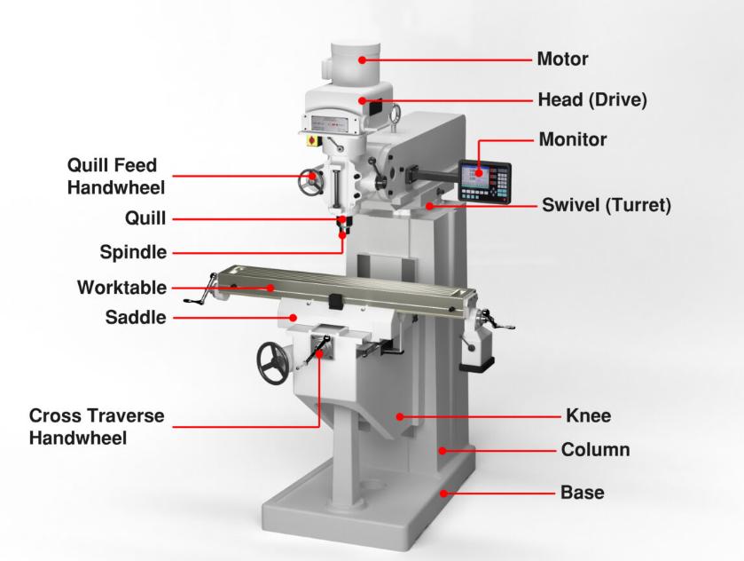
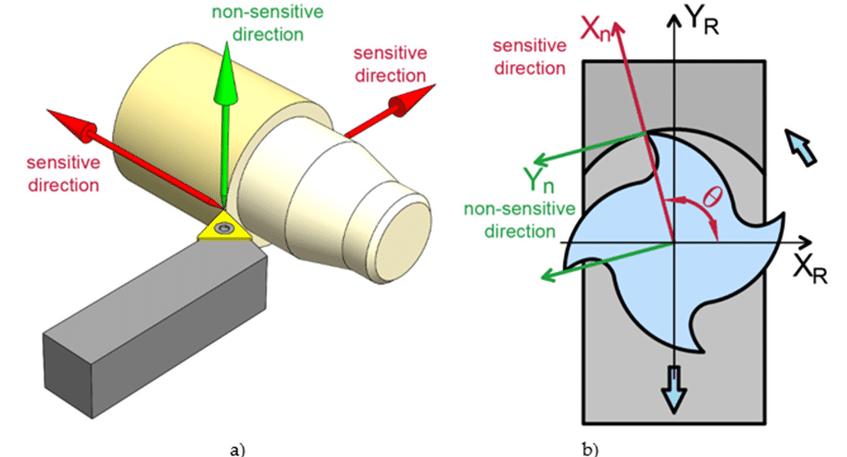
Milling Machine Axis Directions are critical to setting up the tool path and the precision of the interface. It is an essential aspect of intricate CNC mechanisms such as machining centers and milling machines, which meet accuracy levels as low as 0.001 inches. In the X, Y, or Z directions, the tool is aligned for full-on engagement with the material. They must be rigorously altered to keep the profile geometry of the cut. Each flat surfacing project or 3-D sculptor is determined by the axis positions to ensure that the finished item complies with requirements.

Milling machines utilize rotary tools with multiple axes. The spindle rotation in the Z-axis allows for depth adjustment. The tool spins at speeds up to 12000 RPM. Key components include the chuck, collet, and cutter head. Typical tools are end mills, drills, and taps.
In milling machines, material feed direction correlates with the X and Y axes. Operators set the feed rate to align with the tool's speed. This process involves the table, which moves the workpiece precisely under the tool. Common feed mechanisms are ballscrews and servo motors.
Milling operations classify into face, plain, and angular cutting. Each type uses distinct axis movements—X for horizontal, Y for vertical cuts. Machines offer CNC (Computer Numeric Control) for complex tasks. Essential operations include grooving, slotting, and contouring, executed with precision mold programming.
The X-axis in milling machines, as noted earlier, controls horizontal motion across the workpiece. Most side milling and channel cutting operations are supported by this axis. The precision with machine across the X-axis is established by the lead screws and DRO * systems and usually is up to 200.
The Y-axis is associated with the vertical motion of the milling machine. For example, most face milling and slotting operations are performed with the help of this axis. The Y-axis setting includes guide rails and a feed that is maintained through a motor drive. The exact task management is improved with the help of CNC machine to ensure immediate and precise movement limited to the adequate tolerance.
Finally, the Z-axis is about the vertical lift of the milling head. All drilling and plunge milling operations benefit from the Z-axis * as it provides the ability to adjust the depth. It is usually managed with the spindle motor and a ball screw that allow for a clear and smooth depth shift.
The Cartesian plane of the milling machine is associated with a right-angle X, Y, and Z axes intersect, creating a three-dimensional space for material operation. Each axis is calibrated for immediate movement, ensuring exact geometric cuts.

Calibration errors in axis directions directly affect milling accuracy. If the X, Y or Z-axis is inaccurately calibrated, the variations in dimensions can be up to 0.005. Regular calibration checks using laser systems and test artifacts are required. If the field is not calibrated properly, the path taken by the cutting tool is compromised, resulting in variations of finished products. Axis directions are issued to determine the cuts’ precision in the milling process.
Axis directions are important for determining cuts’ precision in the milling process. The X, Y, and Z-axis direction is ensured that the cutter follows contours. Precision is kept low; it is maintained less than 0.010, allowing for finer drawings to be made.
Misalignment in axis directions is too much risk to be taken. Even small misalignments in the X and Y-axis may result in the cuts being taken away at several points, resulting in assembly fits. The need for regular maintenance and alignment checks has been highlighted to ensure that all axes are sterile and responsive.
Error sources in milling include backlash in the X, Y, or Z-axis, thermal expansion, and mechanical wear. These values can create position errors of up to 0.020. Errors are minimized through feedback systems like encoders. This helps to maintain the measurements’ integrity and increase the reliability of the machine by improving overall performance.
The spindle is aligned along the Z-axis, perpendicular to the worktable. The vertical structure is commonly used for plunge and drilling jobs. End mills and face mills are used. The speed can go multiple ways, allowing for multiple tool life and precision when it comes to different materials.
The worktable is lateral to the spindle located on the X-axis. The structure above is more suited for heavy materials–cutting large designs in the workpiece, like slotting or shaping. Horizontal mills include more than one type of cutter which enhances the possibility of different processing options.
Rotary table introduces angular movement, and the axis is called A-axis. It allows for more free-form designs that range beyond the 3-Axis machinery. Later allows for more complex designs and multiple angles without repositioning the workpiece. In freeform milling, the rotary must be precise to provide the best outcome since concentricism and symmetry are crucial factors in the milling process.
The setup of the axes considerably influences the final result. Vertical machining setups deny access but provide good visibility, which is necessary for detailed work. Horizontal setups provide less access but are ultimately more stable. The 4th and 5th axis freed form milling increases dynamics and decreases time in the process.
The term multi-axis machining describes a process where three or more axes are under precise control. As a result, the machine has enhanced ability to produce complex parts while reducing the setup times. The ability to optimize the tool orientation levels alongside the tool’s movement maintains the maximum machining accuracy.
The tool movement is controlled by CNC technology that guarantees the precision of 0.001 all over the X, Y, Z axes. Multi-axis typically has extra rotary axes, named A, B, or C, which increases the capabilities of the machine. These capabilities help people work on complex geometries.
Complex geometries involve the interaction of several axes to achieve detailed designs. The four axes; X, Y, Z, and often rotary, allows the manufacture of complex curves, intricate designs, and impossible molds that three-axis sets cannot create.
Machining handles make high-resolution components possible, such as aerospace parts, and multi-axis complex curves and angles.
Intricate milling tasks involve detailed movements and processes of milling. Some of the intricate tasks are such as engraving, threading, and micro-machining that must have the exact tool position and speed. The CNC handles tool workability, and the involved axes have to maintain tight tolerances, which can be as low as 0.010, to meet the precision components.

Similarly, axis orientation dictates the type of tool alignment for optimal performance. Vertical axes are preferably designed for use with end mills and drills, whereas horizontal axes are specialized for side cutters. Accurate tool alignment along the X, Y, and Z axes ensures that the tool’s cutting edge meets the work surface material from the correct angle to optimize tool performance and work surface finishing.
Cut Patterns are influenced by the axis orientation perspectives. Vertical setups are best used in pockets and profiles due to the consistent side contact that supports the pattern. Horizontal axes are most effective in slotting and facing given the simplicity of the linear pattern. Combined proper alignment of each axis with the optimal spindle direction along the path allows for clean cuts across complex cut patterns devoid of chatter or deviation.
Cutting approach variations are mainly dependent on the axis orientation perspective. The horizontal work surface allows deep, heavy depth cuts along the X-axis, whereas more detailed work can be provided on the Z-axis on the vertical axis. The choice includes understanding the spindle side orientation and the dynamic force created in the process while at the same time optimizing tool life and materials removal.
Tool methods mainly depend on the milling axis. Standard 3-axis production milling does not include advanced processes such as helical milling, which is primarily facilitated by multi-axis tooling setup. The work simultaneously requires specialty tools such as ball nose end mills or steroidal cutters capable of moving along complex trajectories.
|
Factor |
Vertical Axis Orientation |
Horizontal Axis Orientation |
|
Tool Alignment
|
Tools align vertically |
Tools align horizontally |
|
Prefers end mills, face mills |
Uses side and face cutters |
|
|
Cut Patterns
|
Ideal for drilling, plunge cutting |
Best for slotting, peripheral milling |
|
Deep pockets, detailed contours |
Long, straight cuts |
|
|
Cutting Approach
|
Tool moves down into material |
Tool cuts across the material |
|
Precision in depth control |
Broad material removal |
|
|
Tooling Method
|
Requires precise Z-axis control |
Leverages X-axis for feed rates |
|
Suitable for detailed work |
Supports heavy cutting tasks |
|
|
Setup Complexity |
Moderate, depends on depth precision |
High, requires stable setup |
|
Typical Applications |
Mold making, fine engraving |
Heavy machining, gear cutting |
|
Tool Wear |
Higher in plunging and drilling |
Even wear due to horizontal feed |
A Table on How Does Axis Orientation Affect Tool Selection and Setup!

Issues with Wear and Tear Wear Issues -and-tear of the milling machine’s components have a major impact on the axis directions. Components such as the lead screws and guide rails degrade with time, disrupting the precision of the X, Y, and Z axes.
The tool path may deviate as frequently as 0.005 from the desired path, which affects the quality of the cut and part. Frequent evaluation and replacement of these parts are critical to sustaining the integrity of the axial directions.
Maintenance proves to be complex, considering the need to maintain the axis directions. Lubrication, alignment, and backlash adjustments are all carried out.
Failure to perform regular maintenance allows some of the axes to drift, resulting in errors during the machining process. Upon installation, the CNC systems will continue to require frequent updating and calibration to ensure that the axis has the exact command.
Alignment Mishaps in the Axis The axis alignment pose a significant threat to the axis in milling machines. Installation errors, thermal expansion, and mechanical movement all cause misalignment. This form of deviation shifts the position of the tool by several points, resulting in defects in the final product. Calibration should be carried out frequently and strategically to eliminate the axes’ alignment challenges.
Are you are experiencing common axis direction problems? Work on axis direction issues always starts by performing misalignment checks. With precision checking tools like dial indicators, measure the deviations on all three axes; the deviations should not exceed 0.001.
When checking each axis, separately, identify each one’s bias deviations. This measure will indicate where one may need to make mechanical adjustments to the machine, while ensuring each axis is correctly realigned.
Calibration Processes meanwhile, use calibrated laser systems to measure the machine’s positional inaccuracies due to the issues in axis direction. Calibration should be repeated regularly to make sure each axis runs within prescribed tolerances.
This measure is of utmost importance when one is making further mechanical adjustments or replacing the parts.
Maintenance Strategies In the meantime, a periodic upkeep should be put in place, lubricating the machine while tightening the loose components and replacing the worn parts. Such maintenance will lower one’s risk of axis drift while extending the period of use of the machine even further. Ensure regular upkeep by utilizes detailed organized logs.
Finally, try to stop axis direction issues before they even start. Implementation of quality assurance practices such as additional training for the staff members responsible and predictive maintenance software. This measure should lower the downtime of the machine by alerting the user to any issues in advance status.
Milling Machine Axis Directions have a significant impact; they decide on the efficiency and accuracy of CNC machining. Visit CNCYANGSEN for a deeper understanding of how each position impacts operational impacts. Milling Machine Axis Directions must be twisted, rewired, and revamped to aid in tool performance and product integrity. This results in top machining methods and best performance.