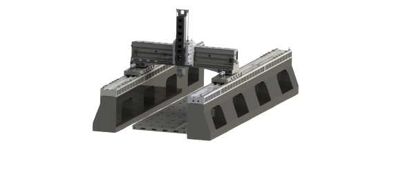
A 5-axis machine is an advanced CNC machining device with five independently moving axes that can be precisely controlled in the X, Y, Z, A and B directions, thereby achieving efficient and high-precision machining of complex parts. This machine tool adds two rotating axes (usually A and B axes) so that the tool can approach the workpiece from any angle, greatly improving the flexibility and efficiency of machining.
The main advantages of 5-axis machine tools: high efficiency, high precision, extended tool life, suitable for complex parts
Max. X-axis Travel :
21000mmMax. Y-axis Travel :
3000mmMax. Z-axis Travel :
1500mmMax Workpiece Length :
20000mmMax Workpieces Width :
3000mmMax Workpieces Weight :
10Application :
Medical IndustryProcessing :
Drilling, Tapping, Milling, Surface MillingYSMT-21042 The Main Structure and Technical Characteristics

The overall layout of the machine tool is a synchronous moving crane type gantry structure, with the workbench fixed and the gantry crane moving forward and backward; the left and right columns and the bed are distributed on both sides of the workbench. The gantry crane moves forward and backward on the X-axis, and the "box-in-box" symmetrical beam structure design.
 |
1. Machine Tool Spindle
The spindle adopts HSKA63 high-speed electric spindle. The spindle has a water-cooled internal cooling method that reduces the thermal deformation of the spindle and improves the stability of the spindle accuracy and the machining accuracy of the machine tool. The machine tool has spindle orientation and rigid tapping functions. The spindle box component adopts a double nitrogen liquid balancing cylinder mechanism to ensure the stability of the spindle box movement.
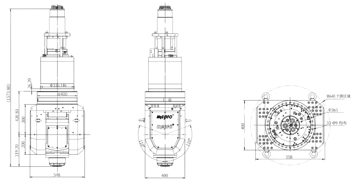
Five-axis linkage double swing milling head: A/C mechanical axis + electric spindle, fork-type integrated structure, with high rigidity, A/C axis adopts unique anti-backlash structure transmission.
2. Feed Transmission of Each Axis The X-axis adopts bilateral double drive, that is, both the left and right slides are equipped with a double motor rack and pinion drive structure, which can effectively eliminate transmission gaps and improve the positioning accuracy and repeatability accuracy of the machine tool. Z-direction transmission uses AC servo motor as the power source and ball screw as the transmission component. The ball screw is fixedly supported at both ends. It is supported by an imported special precision bearing group and pre-stretched in both directions to ensure the feed stiffness and life of the screw. The Z-axis motor has an automatic brake function. In the event of a power outage, the automatic brake will hold the motor shaft tightly so that it cannot rotate. 3. Guide Rail Form The X-axis guide rail pair uses four heavy-duty linear guide rails with small friction coefficient and high sensitivity; small vibration at high speed and no crawling at low speed. The drive shaft has high positioning accuracy and excellent servo drive performance; at the same time, it has large load-bearing capacity and good cutting vibration resistance, which can improve the dynamic characteristics of the machine tool and increase the accuracy, stability and service life of the machine tool; The Y-axis crossbeam guide rail pair uses two heavy-duty linear guide rails; the guide rails are arranged in a stepped manner, with a large span and sufficient bending stiffness and torsional stiffness. The Z-axis guide rail pair uses four heavy-duty linear guide rails and 10 slide blocks to ensure smooth cutting during processing. It adopts a ram 400*420 structure 4. Basic parts of machine tools The bed, columns, beams, spindle box, etc. are all cast using high-strength cast iron materials and resin sand technology. To meet the heavy load cutting of machine tools, the cross beam adopts a large cross-section and has sufficient bending stiffness and torsional stiffness. These large parts are designed optimally with the aid of computer three-dimensional software, and the stiffeners are reasonably arranged to improve the stiffness of the large parts.. |
YSMT-6030-5X CNC Lathe Machining Parameters
| Subject | Specification | unit | YSMT-21042-5X |
| Travel | X/Y/Z axis | mm | 21000*3000*1500 |
| Spindle nose to the worktable surface | mm | 350-1850 | |
| Gantry passable width | mm | 4200 | |
| Worktable | worktable(L*W) | mm | 20000*3000 |
| Worktable max load | t/㎡ | 10 | |
| T SLOT | mm | 36*200 | |
| Spindle | Spindle type | mm | HSKA63 |
| Spindle speed | rpm | 18000 | |
| Spindle delivery type | Electric spindle AC swing five-axis head | ||
| Feed rate | Feed rate ( X/Y/Z ) | m/min | 30/30/30 |
| The max cutting feed rate | mm/min | 6000 | |
| Motor | Spindle motor | kw | 30 |
| Three-axis servo motor | kw | 5.4*4/5.4/5.4 | |
| Cutting water pump motor | kw | 2.7 | |
| ATC(optional) | Tool change method | Side Amount | |
| Tool handle specifications | type | HSKA63 | |
| Tool capacity | tools | 30 | |
| Maximum tool diameter (adjacent tool) | mm | 80 | |
| Maximum tool diameter (without adjacent tool) | mm | 120 | |
| Maximum tool length | mm | 350 | |
| Maximum tool weight | kg | 8 | |
| Fastest tool change time | sec | 2.5 | |
| Accuracy(GB/T 19362.2-2017) | Positioning | mm | 0.03/0.02/0.015 |
| per 2 Meters | |||
| Repeatability | mm | 0.02/0.01/0.01 | |
| per 2 Meters | |||
| Power requirement | Power requirement | kva | 60 |
| Air pressure requirement | Kg/cm | 6~8 | |
| Others | L*W*H | mm | Appr 31600*8130*7950 |
| Weight | T | Appr 228 |
Tags :